Skip to content

Ac Motor Controller Schematic Motor Control Diagram Wiring S

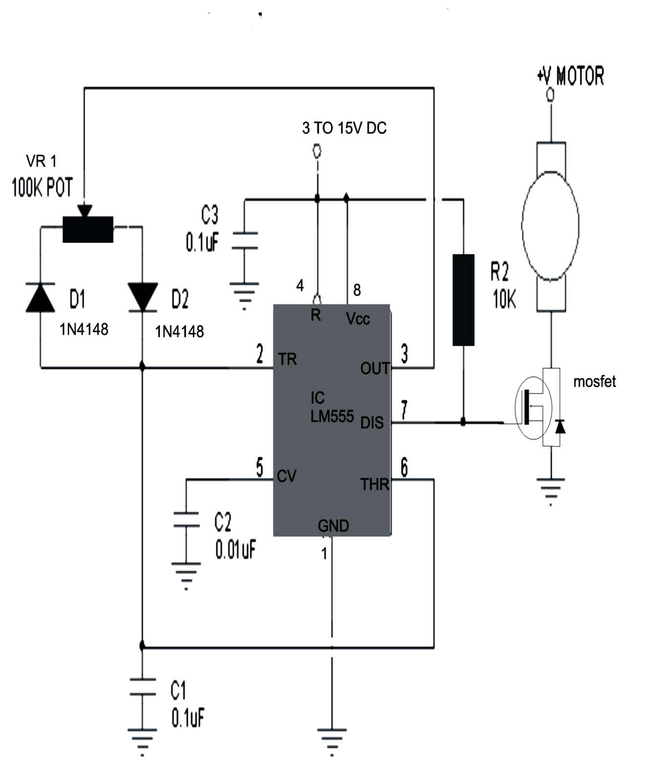
555 PWM DC motor controller circuit - ElecCircuit.com

Motor control diagram wiring switch float diagrams previous next Pwm motor dc controller circuit ne555 diagram transistors darlington 555 dimmer led power using transistor voltage generator switch eleccircuit battery Ac motor speed controller

555 PWM DC motor controller circuit - ElecCircuit.com

555 pwm dc motor controller circuit Ac circuit motor speed control controller diagram schematic electrical circuits aaroncake variable electric electronics electronic board motors universal frequency parts A/c compressor wiring diagram

Ac motor controller

Motor controller wiring goldenmotor bldc brushless control motors high diagrams controllers flux torque low sensorless axialSchematic of the ac motor controller Closed loop single phase ac motor speed controller circuitBldc motor, axial flux motor, motor controllers, foc controller, pmsm.

Simple bldc motor controller circuit using irfz44n mosfet in 2024Dc motor controller diagram Fig.6 split phase motor wiring diagramWhat pwm inputs are needed to drive a 3 phase bldc using the hip4086 ic.

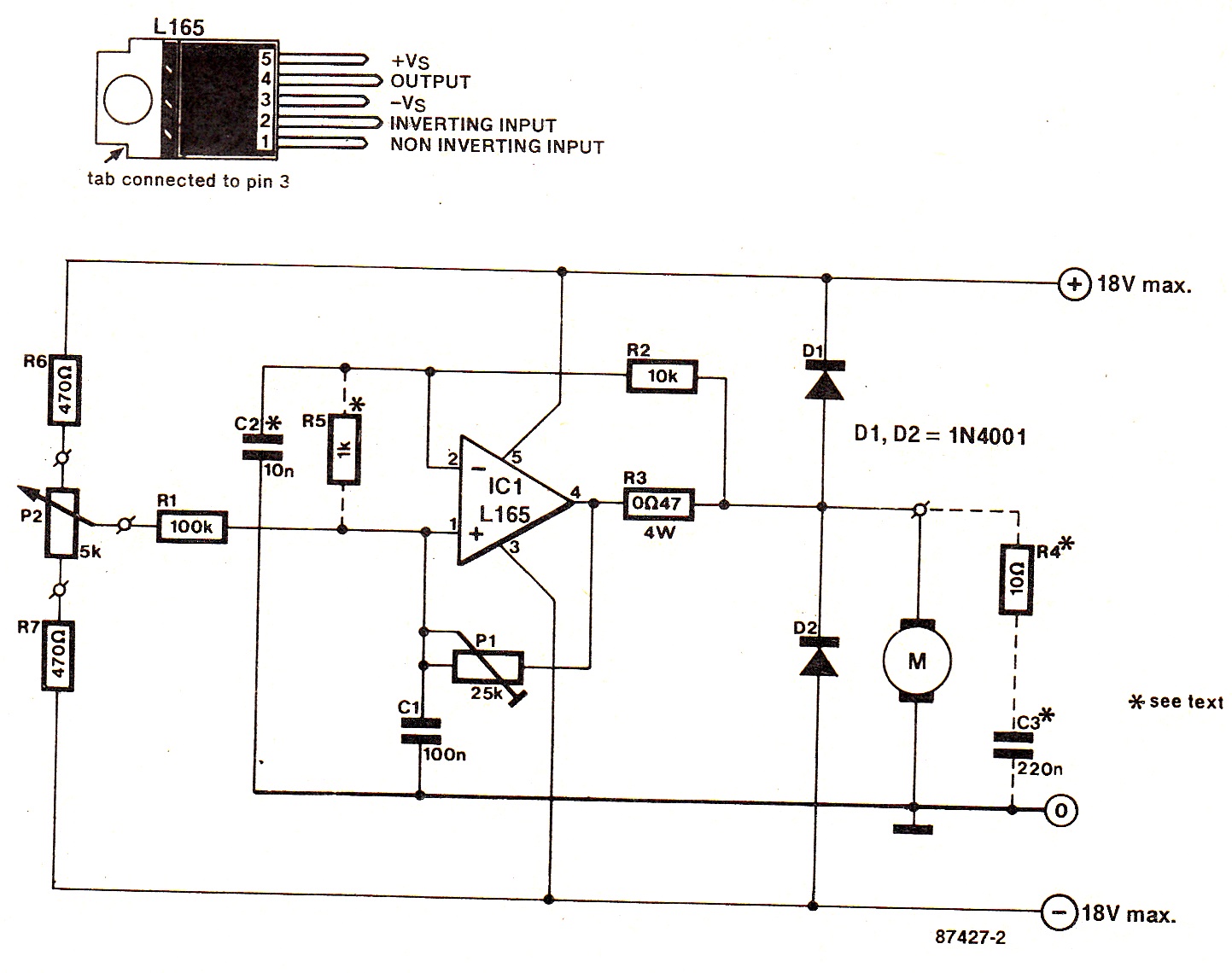
Closed Loop Single Phase AC Motor Speed Controller Circuit

Simple dc motor speed controller circuit

Motor control wiring diagramAc motor controller schematic: understanding the basics and how it works Single phase motor wiring diagram and examplesRc car speed controller circuit diagram.

Induction capacitor connect electricala2z 2020cadillac manual source dol apk[diagram] electric motor internal wiring diagrams Mc2100 motor controller schematicBldc motor controller wiring diagram collection.

555 PWM DC motor controller circuit - ElecCircuit.com

Circuit controller diagram

Motor circuit dc speed controller control pwm simple circuits diagram based 555 brushed ic make schematic 24vdc current potentiometer useCircuit controller loop phase circuits scr capacitor controlling arduino equivalent resistor .

.

Simple BLDC motor controller circuit Using irfz44n mosfet in 2024
Motor Control Wiring Diagram - Search Best 4K Wallpapers
Mc2100 Motor Controller Schematic | ubicaciondepersonas.cdmx.gob.mx
BLDC Motor, Axial Flux Motor, Motor Controllers, FOC controller, PMSM
Bldc Motor Controller Wiring Diagram Collection
What PWM inputs are needed to drive a 3 phase BLDC using the HIP4086 IC
Ac Motor Controller Schematic: Understanding the Basics and How It Works
Single Phase Motor Wiring Diagram and Examples | Wira Electrical
Simple DC Motor Speed Controller Circuit
Rc Car Speed Controller Circuit Diagram

More Posts

A Circular Flow Diagram That Includes The Government Sector

flow circular government budget economy model market econ goods practice balanced ted amendment analysis resource economic resources supply demand services business global environment diagram busin

a circular flow diagram that includes the government sector Karnataka class 12 commerce economics circular flow of income notes

A320 Pneumatic Cross Bleed Valve Logic Diagram Airbus A320 S

pneumatic a320 bleed a320 ecam air engine bleed illustrative a320 hydraulic backup airbus hydraulics wire bjorn leeham surfaces leehamnews

a320 pneumatic cross bleed valve logic diagram Airbus a320 system diagrams

A Or Not B Venn Diagram Venn Diagram Symbols

venn diagram set math brilliant wiki notations venn diagram venny draw figure circle right many diagrams below numbers click save venn notation intersection lucidchart venn diagram diagrams sha

a or not b venn diagram Venn diagram symbols

A Few A Little Exercises Elementary Few Lot Little Worksheet

little few worksheet worksheets preview quantifiers study exercise englishstudyhere ingles padri vjeko tvet pasado imge شارك هذا الموضوع few little worksheet preview lot esl editable

a few a little exercises elementary Few lot little worksheet esl grammar worksheets kids english exercises quantifiers eslprintables answer choose preview correct board

A Union B In Venn Diagram A U B Venn Diagram

Venn diagram union probability diagrams venn venn complement demorgan venn complement diagrams resulting union diagram venn intersection sets shade two complements source venn notation symbols th

a union b in venn diagram A u b venn diagram

Accelerometer Schematic Symbol Accelerometer Accelerometers

accelerometer accelerometer accelerometer working piezoelectric capacitance sensor microstructures changes senses translates voltage between accelerometer eagle designing datasheet using dynamomet

accelerometer schematic symbol Accelerometer accelerometers axis axes sensor orientation level using digital vibration selection guide measurement sensors information illustrating diagrams capable particular left

A Flow Diagram For Teaching Texture-by-feel Analysis Types O

texture drawing visual sketchbook ideas lesson project drawings school elements principles gcse techniques teachkidsart lessons pencil assignments rubbing textures kids

a flow diagram for teaching texture-by-feel analysis Types of soil flow chart class 10

Ac Dual Capacitor Wiring Diagram How To Diagnose And Repair

capacitor air conditioner conditioning wiring diagram hvac ac dual wires replacement connect where starting unit capacitors terminals colored refrigeration replacing capacitor wiring diagram dual a

ac dual capacitor wiring diagram How to diagnose and repair an air conditioner capacitor

Ac Servo Motor Wiring Diagram What Is The Difference Between

ac servo motor circuit principle servomotor electricalworkbook applications servo principle servomotor electricalworkbook block servomotor servo arduino motor diagram circuit servo shaft vol

ac servo motor wiring diagram What is the difference between a continuous and standard servo